
Heatsink Soldering – Laptop Modding Adventure – Part 3/5
YouTube video transcription
[Original source] Partially based on the script of my YouTube videos: https://www.youtube.com/watch?v=3RbwFjBFDVU
[Updated] Contains updated data from 2022.
This guide is compatible with the the following laptops.
[Laptop] XMG Apex 15 Max (2022) with B550 chipset & XMG Apex 15 (2020) with B450 chipset
[Barebone] Clevo NH50VR / NH55VR / NH57VR / NH58VR (B550) & Clevo NH50AF1 / NH55AF1 / NH57AF1 / NH58AF1 (B450)
[Similar laptops] One K56-AR, Eluktronics Thicc-15, Eurocom Nightsky ARX15
[CPU] Zen3 & Zen2 Ryzen Desktop CPUs
[Note] This guide is applicable for Zen3 and Zen2 Ryzen CPUs in the B550 chipset based XMG APEX Max (E22) and B450 chipset based XMG APEX (E20) laptop.
Hi and welcome to part 3 of the laptop GPU modding adventure.
In the second video you saw how I soldered some wires to the laptop’s mainboard to communicate with the GPU VRM’s I2C bus. I learned that the stock VRM temperatures are quite high and that I need to improve them before I can start to raise the power limit of the GPU with a shunt mod to 140W in total, instead of the stock 115W.
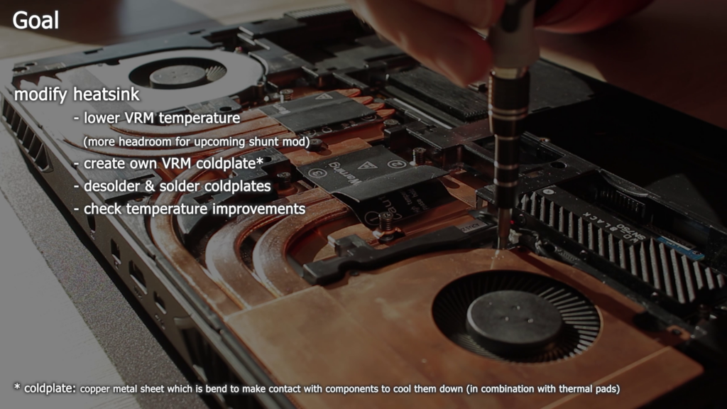
The goal for this video is to modify the heatsink in a way the GPU VRM stay under 100°C, even after the 140W modification. I will attempt to create my own VRM coldplate and replace it with the stock one. Which also means that I need to desolder the old coldplate and re-solder my new one without destroying the heatsink.
And destroying the heatsink is a real danger, since the heatpipes are very sensitive to excessive heat. They usually can withstand temperatures up to 200°C or even 250°C until they swell up and burst. To prevent their destruction I need to pay close attention to the temperatures and raise the heat slowly in a controlled fashion.
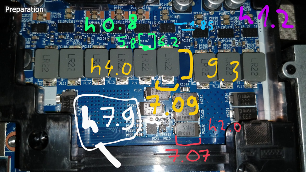
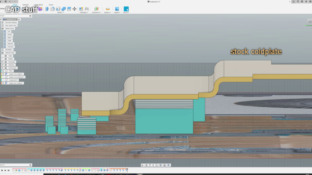
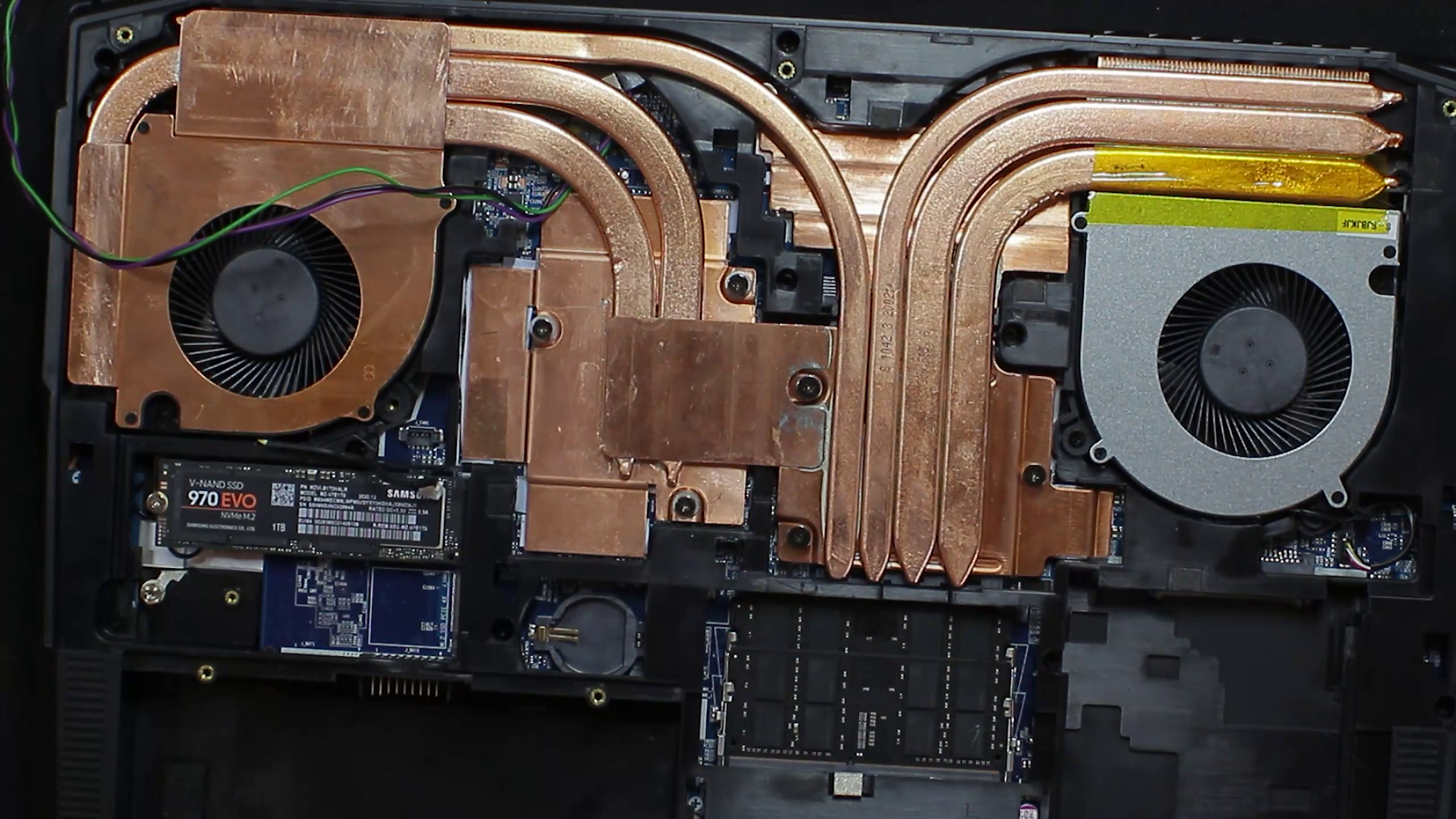
My first action was to take high resolution photos of the area the heatsink needs to fit in and find out about the dimensions of the most critical parts on the PCB and stock heatsink.
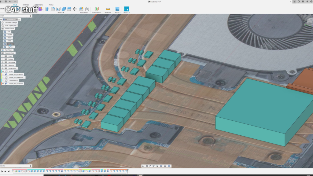
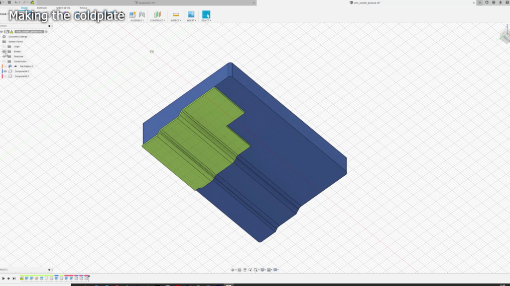
Using these informations I created a minimalistic CAD model to plan my own design.
To get rid off the heat in the VRM power stages quicker i need to improve the thermal transfer. To do so i need to reduce the distance between the coldplate and the power stages and inductors. In the stock configuration the heatsink uses 2mm thermal pads. To see significant improvements I tried to redesign the new VRM coldplate to use 1mm thermal pads, which wasn’t easy.
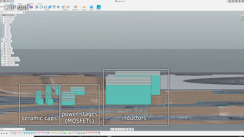
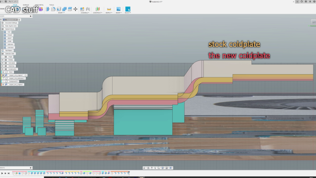
Using the sheet metal tool in Autodesk Fusion 360 I soon realized that I can reduce the gap to less than 1mm for the inductors easily, but wasn’t able to produce a small enough bend radius to come close enough to the VRM power stages than stock. The reason for is that I planned to use a 1mm copper sheet, instead of the original 0.8mm one. And I got no proper sheet metal press to build up enough force to bend the sheet metal to a nice 90 degree stair-shaped coldplate as seen with the stock heatsink.
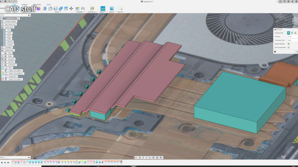
So my only solution was to use a second layer of 1mm copper sheets to make the lower part 2mm thick in total AND come closer to the VRM’s power stages this way. I also increased the size of the lower part in a way I can cool down the closest ceramic capacitors with the heatsink too, and transport a little more heat away from that area in total.
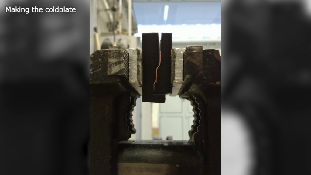
After finishing my sheet metal design I created a press die in Fusion 360 and printed two iterations in PLA on my 3D-Printers. The plan was to use a bench vice to press both blocks together which force the copper sheet into the given shape.
With some force and after two iterations it turned out great.
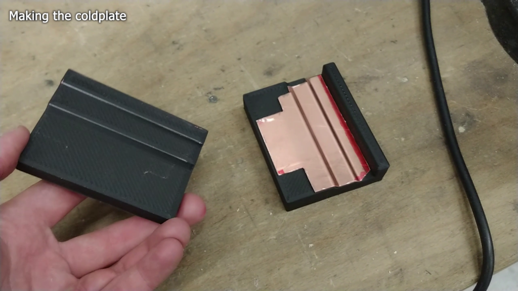
The curves are a bit less pronounced than planned in CAD, but the new coldplate is close enough to my reference 3d print and overall dimensions are fine.
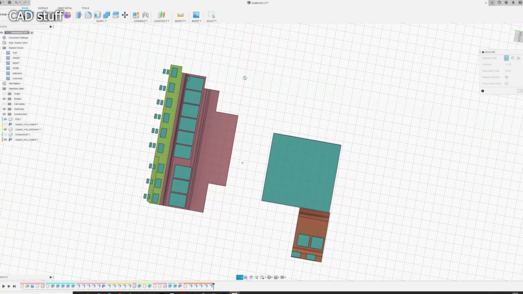
What was left were the little extension plates which guarantee a less than 1mm gap to the VRM’s power stages. I soldered them on with common SMD solder paste which melts at regular solder’s 220°C.
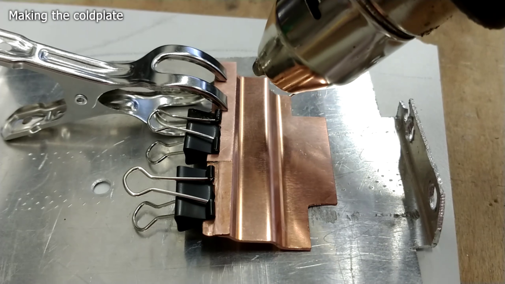
De-soldering the old VRM coldplate was not easy. At first i tried to do it with my cheap SMD hot air gun but it got not enough power. Believe it or not: a copper heatsink got a lot of thermal mass and cools down quickly. WHAT A “SUPRISE”.
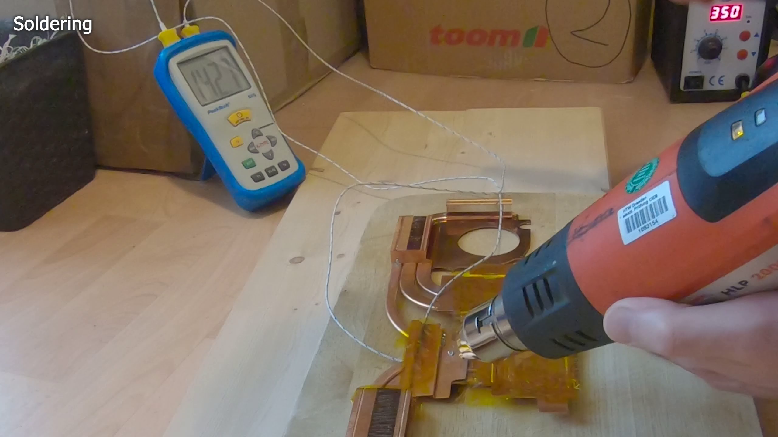
I needed the help of an additional 2kW heat gun to get the job done.
To prevent any unwanted damage to the heatsink You basically NEED a temperature probe to make sure you are not overdoing things. What you really don’t want is to de-solder more things than just the spot you are working on. [Pause] I mounted a temperature probe to the heatpipes and another one to the coldplate under a thick layer of kapton tape. This way I can make sure I hover around the melting temperature on this exact spot and keep the other solder joints on the heatsink colder and solid.
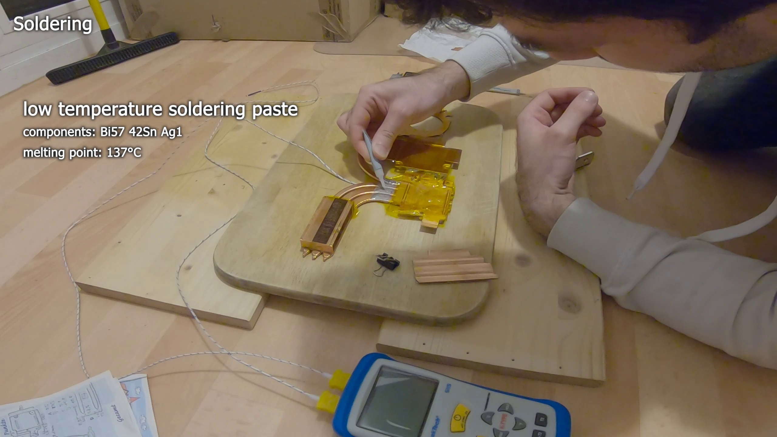
Heatsink components usually are soldered with low temperature solder (Bi57 42Sn Ag1) which melts between 137 and 140°C.
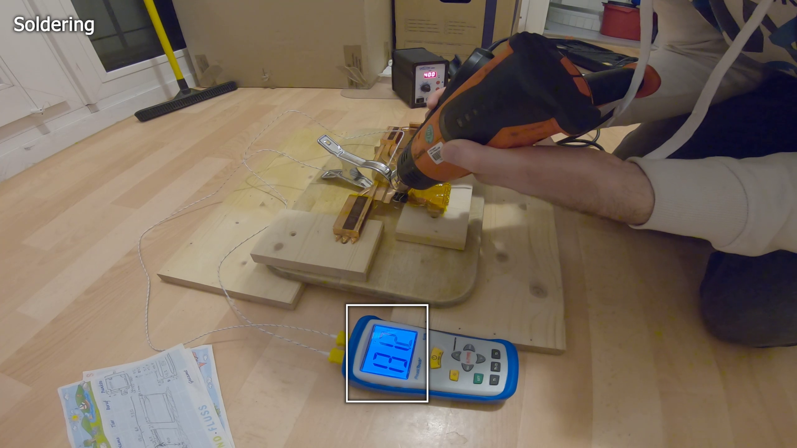
As it reached 140°C, there were a lot of clicking noises which indicated that the solid solder connection between the copper parts began to become loose in some areas. With gentle knocks on the coldplate i tried to find out if all solder joints melted. At around 142°C on the heatpipes the coldplate finally became loose.
Because there is not much wiggle room between the heatsink and the laptop’s frame I tried to align the new coldplate as precisely as possible.
The re-soldering was done with the help of very similar low-temperature soldering paste, which usually is used for heatsinks. The re-soldering process was much easier and quicker, because the thermal transfer between the coldplate and heatpipes was much worse with the paste in between than with the solid solder before.
As soon as i reached the melting temperature range, the temperature dropped off quickly which I thought was the indication that the solder paste melted.
After the heatsink cooled off i saw that it melted indeed and the re-soldering was successful.
So let’s drop in the heatsink and find out if i achieved any improvements over the stock heatsink.
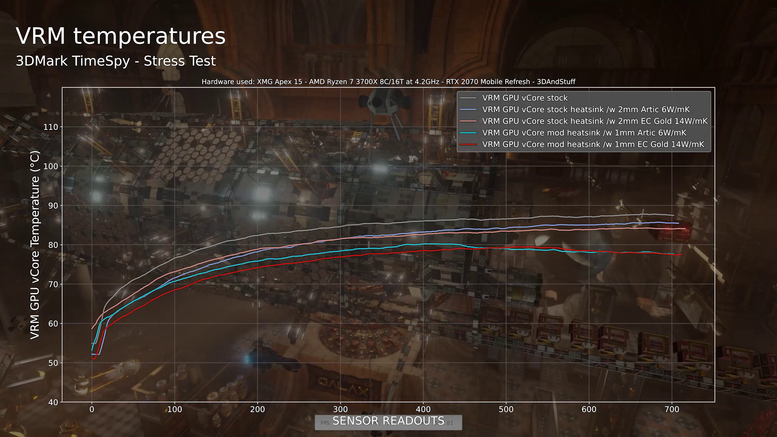
As seen in part 2 we measured up to 95°C on the GPU Core VRM in Cyberpunk 2077 with the stock heatsink. Using the modified heatsink I managed to drop the temperature down to just 86°C.
But I must note that I used other thermal pads than the stock ones. In the line-plot you can see a line recorded with 1mm Artic Thermal Pads with 6W/mK and with high-end 14W/mK EC Gold ones. [Small Pause] Both lines are so close together that it makes no sense to pay the premium for the EC Gold thermal pads. INTERESTINGLY I also compared both thermal pads in 2mm thickness with the stock heatsink and it turns out that it does make a difference there. I am not sure why the results are so close together with my modded heatsink though. I expected at least a very small difference. But maybe I am already to close to the thermal transfer limits of the power stage ICs and I can’t run them colder since the VRM coldplate is connected to the heat output of the CPU and GPU anyway.
Another interesting thing is that the VRM temperatures with the modded heatsink running TimeSpy seem to drop when the fans kick in.
Nevertheless the results are good and should give me enough headroom to run the VRMs in a safe temperature range after I shunt mod the GPU to 125W in the first and 140W in the second step. I hope I can operate them with less than 110°C or even 100°C to make sure the system can withstand the higher loads and could be operated at 140W TGP daily without any hickups or shortfalls.

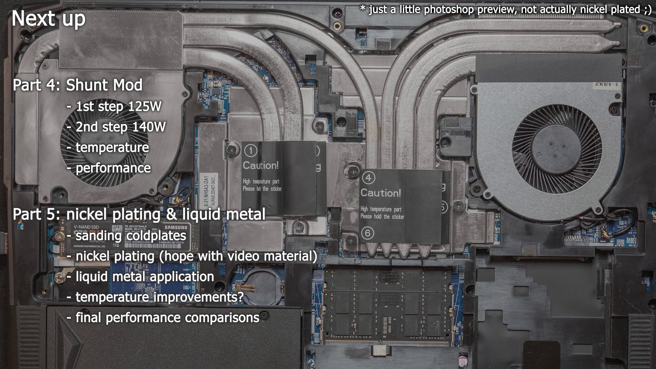
Okay… We are coming to an end for this video, .. but the next one will FINALLY show my attempt to increase the power limit of the GPU with a shunt mod. I will show you how it’s done and what effect it got on our performance and temperature.
After all modifications are working properly I will finally sand down the heatsink’s coldplates and send it to a company which will nickel plate the heatsink. Why nickel plating? Well, because I want to use liquid metal without any side-effects.
Sure, you can use liquid metal on bare copper, but it will kind of dry out over several months and need some re-application over time. Using nickel as a diffusion layer we can make sure the liquid metal will not react with the copper. Instead it should stay where it is and would not require any maintenance for some years. Nickel plating is not necessary to use liquid metal, but it surely is the cleanest way to do it.